You have drilled to 350 feet. The driller's report confirms water. Now a 15 HP, 15-stage submersible pump set is being lowered into the borewell on a column pipe, cable spiralling alongside it, disappearing into darkness. You switch on the panel. Water comes out of the delivery pipe in seconds.
But what happened underground in those seconds? What is actually happening inside that slender cylinder hanging 300 feet below ground to push water all the way to your overhead tank on the fourth floor?
This article gives you the complete, technically accurate answer.
The Pump Set: Two Machines in One
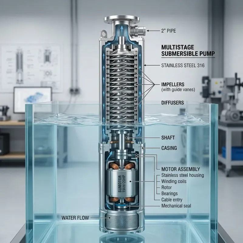
A submersible pump set — often called a "pumpset" in the Indian trade — is the combination of two distinct machines sealed in a single cylindrical assembly:
- The Motor — converts electrical energy into rotational mechanical energy
- The Pump — converts rotational energy into hydraulic pressure (the force that moves water)
These two are coupled on a common shaft. The motor sits at the bottom (deepest point), with the pump section directly above it. Water enters the pump from the sides above the motor and is pushed upward.
Part 1: The Motor — The Engine Underground
Construction
A submersible motor is a highly engineered sealed unit, designed to operate fully immersed in water, often under high pressure, for years without maintenance access.
Stator: The fixed outer assembly containing copper windings. Depending on the phase (single or three-phase), the stator has one main winding with an auxiliary starting winding (single-phase), or three balanced windings offset 120° apart (three-phase). These windings create the rotating magnetic field that is the motor's fundamental operating principle.
Rotor: The spinning inner assembly. The rotor is an induction rotor — it does not have windings connected to external electrical supply. Instead, the rotating magnetic field from the stator induces electrical current in the rotor's conductive bars (by Faraday's Law of Electromagnetic Induction), generating a force that makes the rotor spin.
Shaft: The rotor is mounted on a hardened steel shaft that extends upward into the pump section. The pump's entire impeller stack is mounted on this same shaft.
Cooling: Because the motor is fully submerged, the surrounding well water acts as a continuous coolant, drawing heat away from the motor housing. This water-cooling effect is one reason submersible motors can run continuously for far longer than surface-mounted motors of equivalent HP, which rely only on air cooling.
Sealing: The motor housing is hermetically sealed with multiple mechanical seals to prevent well water from entering the stator windings. A failed shaft seal is one of the leading causes of motor failure — water infiltration destroys winding insulation rapidly.
Lubrication: Most submersible motors are oil-filled (oil provides lubrication for shaft bearings) or water-lubricated (a small amount of clean water fills the motor for lubrication and cooling). Oil-filled motors have better lubrication properties; water-lubricated motors are cooler and simpler to service.
How the Motor Creates Rotation
When three-phase AC power (415V, 50Hz) is applied to the three stator windings, it creates a rotating magnetic field that completes one full rotation per electrical cycle. At 50 Hz with a 2-pole motor, this is 3,000 RPM synchronous speed. Due to slip (the difference between the rotating field speed and the actual rotor speed), most 2-pole submersible motors run at approximately 2,880 RPM at full load. Four-pole configurations run at approximately 1,440 RPM — used for higher-flow applications where a slower, larger impeller diameter is more efficient.
This rotational speed — roughly 2,880 or 1,440 revolutions every minute — is the energy source that drives the entire pump section above the motor.
Part 2: The Pump — Turning Rotation into Water Pressure
This is where the physics becomes fascinating. The pump section contains the stages — and each stage is a carefully designed hydraulic machine.
What is a Stage?
A stage is one impeller-diffuser pair:
Impeller: A rotating wheel with curved vanes, mounted directly on the motor shaft. Water enters through the central eye of the impeller. As the shaft spins at ~2,880 RPM, the impeller's vanes fling water radially outward with enormous centrifugal force, dramatically increasing the water's velocity (kinetic energy).
Diffuser (or Bowl): A stationary component that surrounds the impeller. Its purpose is pure energy conversion: it captures the high-velocity water from the impeller and decelerates it through gradually expanding channels. By slowing the water down, it converts velocity (kinetic energy) into pressure (potential energy).
This is Bernoulli's Principle in direct application: pressure and velocity are inversely related in a flowing fluid.
The Multi-Stage Principle: Why More Stages = More Depth
A single impeller-diffuser stage can only generate a limited pressure boost. For a typical 4-inch submersible pump impeller running at 2,880 RPM, one stage might generate approximately 10–15 metres of "head" (hydraulic pressure expressed as an equivalent height of water column).
If your borewell is 150 metres deep and you need additional head for friction losses in the pipe plus height to the overhead tank — say you need 180 metres total head — a single stage cannot do it.
The solution: stack stages in series on the same shaft.
Water exits Stage 1 at elevated pressure. Instead of leaving the pump, it enters the eye of the Stage 2 impeller. Stage 2 adds another 10–15 metres of head. Then Stage 3 does the same. Then Stage 4. Each stage adds incrementally to the cumulative pressure.
This is identical in principle to how water is pumped through a series of reservoirs, each at a higher elevation — the same energy addition, repeated.
Real-World Example: A Varuna V6 15HP 15-Stage Pump
Let us trace exactly what happens in a Varuna V6 15HP 15-Stage submersible pump — a popular choice for deep commercial borewells in Gujarat.
Specifications (approximate):
- Motor: 15 HP (11.2 kW), three-phase, 415V, 50Hz
- Diameter: 6-inch nominal
- Stages: 15
- Impeller material: High-grade engineering thermoplastic (glass-filled noryl) or stainless steel
- Rated flow: ~6,000–9,000 litres per hour (depending on head)
- Rated head: ~180–220 metres (Total Dynamic Head)
- Shaft speed: ~2,880 RPM
What happens when you switch it on:
The panel closes the circuit — 415V three-phase power flows to the motor at the bottom of the borewell. The Star-Delta starter first connects the motor in Star configuration (reduced voltage, lower starting current) to gently bring the shaft up to speed.
The motor energises — within 2–3 seconds the shaft reaches ~2,880 RPM. The Star-Delta starter switches to Delta (full voltage). The motor now runs at full power.
Stage 1 intake — Water enters the pump through intake ports above the motor. It flows into the eye of the first impeller.
Stage 1 action — The first impeller, spinning at 2,880 RPM, accelerates water radially. The diffuser converts velocity to pressure. Water emerges from Stage 1 at approximately 14 metres of head pressure — about the same as a 14-metre-tall water column pressing down.
Stages 2 through 15 — The water is sequenced through 14 more impeller-diffuser pairs, each adding another ~14 metres of head: 14 × 15 stages = 210 metres of total head capacity at design flow.
Water exits the pump at the top at 210 metres of head pressure — enough to lift water from 350 feet below ground, push it through 200 metres of column pipe, exit at the surface, travel through a delivery line, and fill an overhead tank on a three-storey building with pressure to spare.
The column pipe — attached above the pump — carries the pressurised water upward. Every 10 metres of column pipe hangs approximately 2.5 kg of water weight. With 100 metres of column pipe, the motor must work against 25 litres of water weight in the pipe constantly — the pump delivers enough pressure that this is easily overcome.
Understanding Head, Flow, and the Pump Curve
Every pump has a fundamental performance relationship: as head (pressure) increases, flow decreases. This is the pump curve.
At maximum head (the pump is lifting to its absolute limit), flow drops toward zero. At zero head (water exits at surface level with no height or friction to overcome), flow is at its maximum.
For a 15-stage V6 Varuna pump:
- At 180 metres head: ~8,000 litres/hour
- At 200 metres head: ~5,000 litres/hour
- At 210 metres head: ~2,000 litres/hour (near shutoff)
Why this matters for installation: If your actual operating head (depth + friction losses + delivery height) exceeds the pump's rated head, flow drops dramatically and the pump works under strain. Your pump contractor must calculate Total Dynamic Head (TDH) accurately before selecting a pump:
TDH = Static Water Level (depth to water) + Friction Head Loss in Pipes + Delivery Height to Tank
The most common error in pump selection is choosing a pump based on borewell depth alone — ignoring friction losses in undersized column pipes and the height to the overhead tank. A pump "rated for 200 metres" may deliver only 60% of its rated flow if actual TDH is 210 metres. Always provide your contractor the full delivery height, not just the borewell depth.
The Column Pipe Connection
The pump is connected to the surface via column pipes — threaded UPVC (Class 6 or Class 10) or GI pipes screwed together in sections. A typical installation:
- Each column pipe is 3 metres long, threaded male at one end, capped female at the other
- Sections are assembled as the pump is lowered into the well — one pipe at a time
- The delivery flange at the surface connects to the horizontal delivery line and storage system
The choice of Class 6 vs. Class 10 UPVC depends on the pump's rated head pressure. Class 10 pipes are rated for higher internal pressure and are mandatory for high-head deep-well installations.
The Complete Pump Set, Assembled
From bottom to top, a complete installation consists of:
- Submersible motor — sealed, oil or water-lubricated
- Pump stages — 1 to 25 stages depending on specification
- Strainer/well screen — filters coarse sand from entering pump
- Delivery check valve — prevents backflow when pump stops (critical for multi-stage pumps)
- Column pipe — one section per 3 metres of depth
- Flat submersible cable — runs alongside column pipe, clamped every 3 metres
- Delivery flange and bend — transitions from vertical to horizontal at surface
- Control panel — at surface, manages start, stop, protection, and automation
Conclusion
The submersible pump set is one of the most reliable and quietly remarkable pieces of engineering in everyday Indian infrastructure. The sealed motor, the 2,880 RPM shaft, the careful multiplication of pressure through 15 stacked impeller-diffuser pairs — all working together, submerged in darkness 300 feet underground, to deliver water reliably at every tap in the building above.
Understanding this mechanism helps you make better decisions: the right number of stages for your depth, the right column pipe class, and the right control panel to protect the motor that makes it all work.
At Xanausun, we supply complete pump sets — Varuna, KSB, Kirloskar, and Grundfos — alongside column pipes (Astral UPVC Class 6 and Class 10), flat submersible cables, and L&T control panels. Our team can help you select and specify the exact system for your borewell depth and delivery requirement.